O 10v Dimming Wiring Diagram
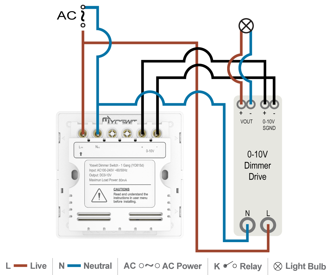
Once complete, turn main power on. When both wires are not touching, the dimming control output will be 10 volts, or 100%.
Lutron 0 10v Dimmer Wiring Diagram
Horizontal beam diagram 5 ft (1.5 m) 5 ft (1.5 m) 0 10 ft 10 ft (3 m) (3 m) 10 ft (3 m) 20 ft (6 m) 15 ft.

O 10v dimming wiring diagram. The first class wiring would be a line voltage switch, that basically turns the device on and off. Not doing so can cause the driver and the fixtures to. Ensure zluhv duh ¿upo\ dwwdfkhg dqg wkhuh lv qr h[srvhg frsshu 2.
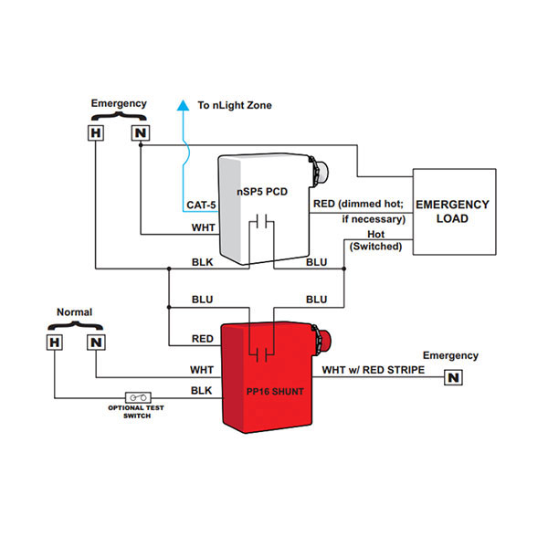
Dimming with on/off control wiring diagram using relay figure c1: You would need to run low voltage wires from the light back to the switch. The class two wiring would be to allow low voltage dimming control, by providing input to which minimum (0v) and maximum (10v) output can be generated.
Led dimming driver wiring diagram created date: Determine locations to install the driver, fixture and control. Install additional components and accessories.
Dimming with on/off control via relay connect the control as shown in figure c2. 1 component 3 components budget friendly costly 20 minutes 5 10 15 20 25 30 35 40 45 50 55 0. Erp offers dimmers with all three dimming options but we do not recommend using more than one dimmer at the same time.
Refer to the wiring sheet included with the relay for more information. Wiring diagram not merely offers in depth illustrations of everything you can do, but also the methods you should stick to while performing so. Unit h huntley, il 60142 u.s.a.
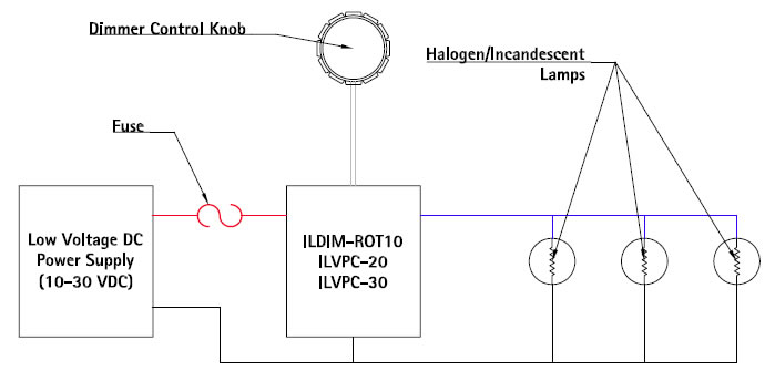
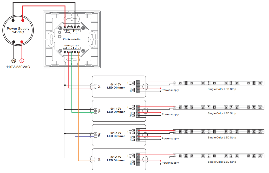
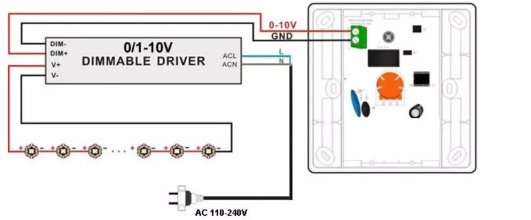
And connect as per wiring diagram. Pwm constant voltage output current: Simply put, the control signal is a dc voltage that varies between zero and ten volts.
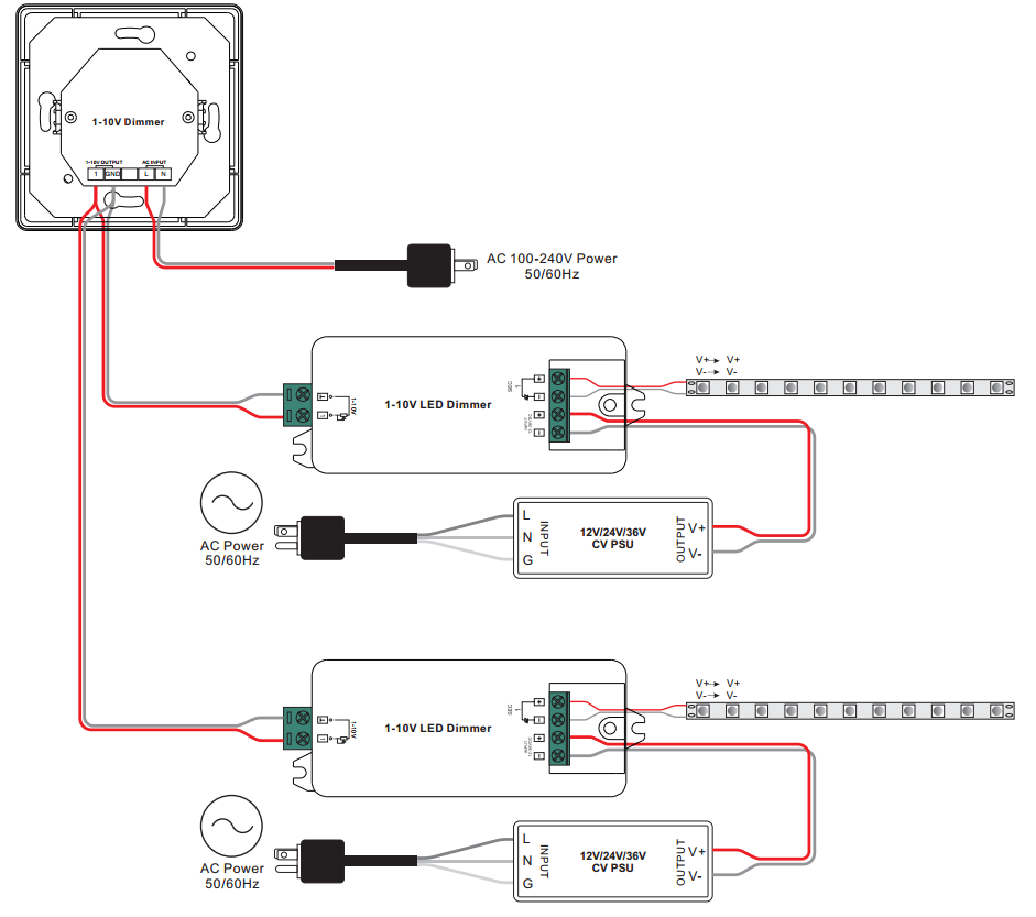
If desired, change switch color. The dimming signal is usually connected to the lighting driver with a purple wire, which carries the 10 volt charge, and a grey wire, which is the common wire carrying the signal. Same class wiring installation shown white orange/yellow black
Lutron diva dvstv v dimmer for fluorescent and led the lutron diva dvstv is a v dimmer that easily lutron dvstv v installation instructions. Ground wire to make a secure connection to the safety ground of the electrical the control4® v dimmer operates independently or as part of a control4. Lutron 0 10v dimmer wiring diagram.
The dimming signal, which is connected to the source (driver) typically has a purple wire that represents +10 volts and a gray wire representing the signal. Www.moduled.io product specifications subject to change without notice Gently place the wires and your device into the wall box and attach with screws provided.
Wiring Diagram 1 0 10 Volt Dimming Wiring Diagram

010vdimmingsystem MOONS' SPARK
Q38P 010V Wiring Diagram_ES Power LED Driver

32 0 10 Volt Dimming Wiring Diagram Wiring Diagram List
0 10 Volt Dimming Wiring Diagram Hanenhuusholli

Scopri 010V DIMMER LED 4Ch. 010_4ch per l'illuminazione Arena Luci
eCoveLine XL 010V by Solid State Luminaires
AC Input 110V Rotary Dimmer SR2202N110V

010V LED Dimmer module SLDDIM1B HUEDA™ LED

1 10v Dimming Wiring Diagram
32 0 10 Volt Dimming Wiring Diagram Wiring Diagram List

010v PWM dimming problem
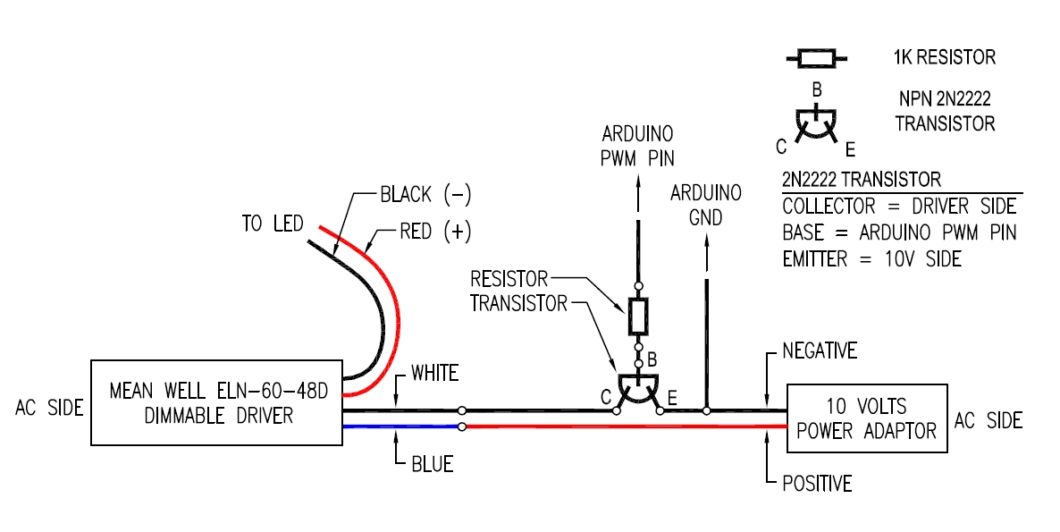

0 10V Dimming Wiring Diagram Led Driver 12v 36w With 1 10v 0 10v 10v Pwm Resistor Or Push Dim
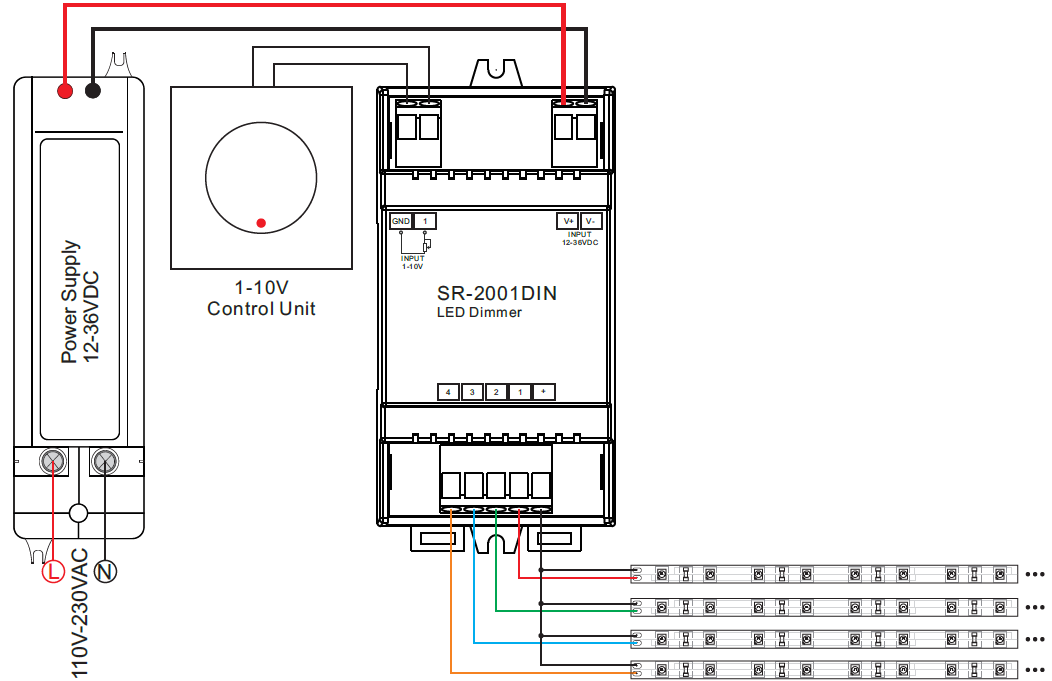
Din Rail Mounted 4 Channel 0/110V LED Dimmer SR2001DIN
0 10v Dimming Wiring Diagram Atkinsjewelry
86*86 Size Knob Type LED Dimmer Switch For LED Lighting 0 10V Analog Signal from china
DIM14 LED Dimmer, 010 Volt Controlled, PWM, 12V 24V Low Voltage 10A
31 0 10 Volt Dimming Wiring Diagram Worksheet Cloud

0 10 Volt Dimming Wiring Diagram